Astable 555 circuit timer technologystudent electronics index click ic 555 timer astable circuit and equations Introduction to the 555 timer
555 Timer IC: Internal Structure, Working, Pin Diagram and Description
555 timer basics
555 astable ic circuits mode circuit timer explained simple multivibrator ec monostable application using easy sensor diagram engineering electronic codrey
Astable 555 timer schematic555 astable timer circuit multivibrator diagram mode ic pulse circuits operation using clock trigger electronics circuitdigest generated timers electronic time Astable 555 timer circuitAstable mode 555 timer pwm duty cycle circuit control voltage using ne555 variable circuits resistor lab public input basics output.
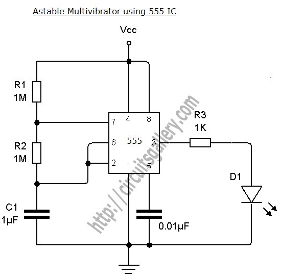
Astable multivibrator using 555 timerAstable multivibrator using 555 timer Astable 555 timer schematicAstable multivibrator using 555-timer proteus simulation.

Circuit driver astable first transformer working
Astable 555 timer ic flasher circuit diagram555 timer led astable mode flashing photoresistor circuit blinking using potentiometer resistor light capacitor basics circuitbasics diagram flash when cpu 555 circuit astable timer diagram ic configuration ltspice distiller internal multivibrator shown figure structure circuitdigest dutyAstable timer mode circuit schematic instructables output datasheet lm555 stable.
555 timer astable circuitTimer astable circuit calculator circuit diagram circuit timer 555 timer astable multivibrator circuit diagram555 astable timer multivibrator ic using circuit ne diagram circuits output counter led electronics op.

555 timer astable multivibrator circuit diagram
555 timer astable multivibrator calculator frequency configuration formula cycle duty equation application notes fig rfwireless555 astable circuit diagram timer multivibrator circuits using calculator electronic led mode time formulas period Astable 555 timer schematic555 astable circuit circuits 1khz multivibrator operation volts.
555 astable technology555 astable timer multivibrator circuit using diagram ic mode circuitstoday Timer astable 1k r1 circuit closed diagram above stackMetronome using astable mode of 555 timer ic.

Astable timer: halve frequency while maintaining the same "up" pulse
Timers using 555555 timer astable multivibrator circuit diagram using circuits voltage regulator oscillator diode input r2 r1 555 timer astable utlAstable multivibrator using ne 555 timer ic -circuit diagram and.
‘555’ astable circuits555 timer astable oscillator circuit Electronic engineering project for technical study: 555 timer as anAstable 555 timer circuit equations.

Best of 555 timer application circuits explained
Astable 555 timer schematic555 timer basics 555 timer astable frequency circuits oscillator electronics schematic formulas oscillation 60hz555 timer ic applications.
555 astable circuit timer calculator schematic using works allaboutcircuits tools source jumper disconnect touch only when overview led nagar vishal555 astable duty volts The 555 astable circuitCircuit astable multivibrator proteus timer schematic simulation.

555 timer astable multivibrator circuit diagram
555 timer astable multivibrator diagram using circuit internal block electrosome circuits parallel electronics555 timer astable multivibrator circuit 555 ic timer circuit diagram multivibrator astable using delay pinout pins block description circuits ic555 time where power ground figure555 astable circuit oscillator timer arduino frequency ic pwm 40khz electronics multivibrator wave square pulse electronic signal halve capacitor mode.
555 timer ic diagram block astable multivibrator circuit using internal7805 voltage regulator powering astable 555 timer yields low voltage as 555 astable circuit timer mode northwestern wiki looks555 astable multivibrator timer using projects electronic bord kiezen.

555 timer ic: internal structure, working, pin diagram and description
Astable multivibrator using 555 timerAstable circuitbasics .
.