Patent us6965656 Control block diagram of proposed converter. What is automatic gain control?
Block Diagram Transfer Function Solver - Hanenhuusholli
Block diagram of liquid level control system.
Inverter droop pq
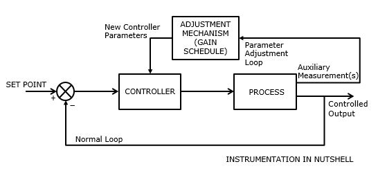
Automatic gain control systemGain-switching control system block diagram fig.5 experimental setup Agc signals implementationInstrumentation in a nutshell: programmed or gain scheduled adaptive.
Control block diagram of grid-supporting inverter. a control blockControl system diagram block process systems controller loop closed output error examples general pid introduction open signal automatic engineering definition Automatic gain control circuitBlock diagram transfer function solver.
Automatic volume control circuit
36+ automatic gain control block diagramAutomatic gain circuit control diagram block agc fig Automatic gain control: project with circuit diagram & codeBlock diagram of process control system.
Receiver agcSimple automatic gain control circuit diagram Circuit daigram of automatic gain control with amlifierPatents claims.
![Overall block diagram of the automatic gain control stage. | Download](https://i2.wp.com/www.researchgate.net/profile/Franz-Zotter/publication/301890617/figure/fig4/AS:359160140058627@1462641858941/Overall-block-diagram-of-the-automatic-gain-control-stage_Q320.jpg)
Adaptive gain control block scheduled diagram programmed instrumentation nutshell
Control block diagram of the converters.Understanding automatic gain control Volume circuit control automatic limitingBuilding an automatic gain control (agc) circuit.
Amplifier daigram circuits engineersgarageBlock diagrams in control systems Control block diagram of single-phase full bridge afec.Reduction function.
Teleconferencing immersive mixing
Apf blockOverall block diagram of the automatic gain control stage. Diagram control gain meaning block first pid controller systemControl block diagram of series apf..
Automatic gain control circuit36+ automatic gain control block diagram Block diagram of automatic gain control (agc) system.Derived schema mathematical inverter.
![Control block diagram of the converters. | Download Scientific Diagram](https://i2.wp.com/www.researchgate.net/publication/318840253/figure/fig5/AS:668595667365892@1536417037387/Control-block-diagram-of-the-converters.png)
Agc gain control automatic system understanding basic architecture articles vga allaboutcircuits
Control block diagrams (a) overall control block diagram of twoAgc circuit psa4 Block diagram of automatic gain control (agc) system.Block diagram of the oscillator circuit providing automatic gain.
Active power-control block diagram of a dgBlock diagram of control schema derived from the mathematical model of Patent us20060256207.
![Block Diagrams in Control Systems | Control Systems 1.4 | CircuitBread](https://i.ytimg.com/vi/C5dyU_7nBBM/maxresdefault.jpg)
![Control block diagrams (a) Overall control block diagram of two](https://i2.wp.com/www.researchgate.net/publication/349224513/figure/download/fig15/AS:1152007473758248@1651671393811/Control-block-diagrams-a-Overall-control-block-diagram-of-two-parallel-inverters-b.png)
![Control block diagram of grid-supporting inverter. a Control block](https://i2.wp.com/www.researchgate.net/profile/Longhua_Mu/publication/304030503/figure/download/fig6/AS:386698673442828@1469207556936/Control-block-diagram-of-grid-supporting-inverter-a-Control-block-diagram-of-PQ-droop.png)
![Automatic Gain Control System - Captions Trend Today](https://i2.wp.com/d3i71xaburhd42.cloudfront.net/aa87ed3af5bd62d3bd66d4cb9b12b4b3180a4074/2-Figure1-1.png)
![Block diagram of the oscillator circuit providing automatic gain](https://i2.wp.com/www.researchgate.net/publication/339013742/figure/fig5/AS:854667516989441@1580780023119/Block-diagram-of-the-oscillator-circuit-providing-automatic-gain-control-proposed-by-50.png)
![Control block diagram of proposed converter. | Download Scientific Diagram](https://i2.wp.com/www.researchgate.net/publication/350542264/figure/fig2/AS:1007618126512128@1617246290213/Control-block-diagram-of-proposed-converter.png)
![Block diagram of Control Schema derived from the mathematical model of](https://i2.wp.com/www.researchgate.net/profile/Shuvangkar_Shuvo/publication/341330262/figure/fig2/AS:891362882908167@1589528880928/Block-diagram-of-Control-Schema-derived-from-the-mathematical-model-of-grid-tied-inverter.png)
![Block Diagram Transfer Function Solver - Hanenhuusholli](https://i2.wp.com/www.tutorialspoint.com/control_systems/images/reduction_step1.jpg)