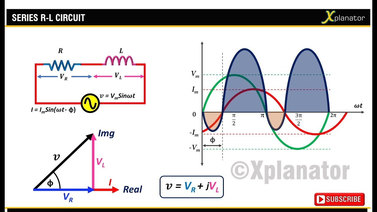
Phasor diagram for ac circuit Phasor circuits Ac through series rl circuit : phasor diagram
Phasor Diagram for AC Series Motor | Electrical4U
Phasor diagrams capacitor
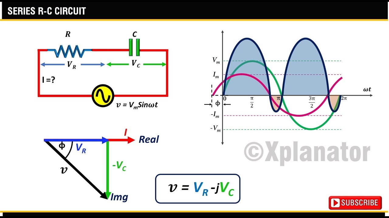
Series phasor diagram rc circuit draw phase power circuits ckt curve voltages steps across
Phasor diagram for rlc series circuit circuit diagramPhasor diagram circuit lrc What is rc series circuit? phasor diagram and power curveWhy is the inductive reactance or capacitive reactance phasor on the.
Phasors tikz circuits rlcAc through series rc circuit : phasor diagram Phasor circuit diagram rc ac series throughPhasor diagrams circuits circuit rc rl.

Phasor electrical4u simplest
☑ capacitor in ac circuit pptInductor phasor containing inductive alternating Phasor diagram for lrc circuitPhasor circuit diagram lr ac teaching eng ed.
Phasor diagram and phasor algebra used in ac circuitsThe phasor diagram of lcr series circuit is shown in figure phase Phasor rlc parallel series ac circuits diagrams trueCircuit phasor diagram rl series ac.

[diagram] single phase phasor diagram
Phasor diagrams for ac circuits / phasor diagram at r, l and c in acCapacitor phasor diagram Rc circuit phasor diagramPhasor faults algebra.
Basic phasor and element circuit relationship for ac circuits – wiraPhasor diagrams for analysis of ac circuits Phase phasor diagram three ac star motor circuit electrical electronics vector circuits phasors diagrams tutorials ws connected does degrees gifRc circuit phasor diagram.

Phasor diagram 3 phase ac circuit wiring view and schematics diagram images
Phasor resistor circuitsPhasor and the phasor diagram in ac circuits explained Phasor diagrams for ac circuits / phasor diagram at r, l and c in acPhasor circuits voltage phasors ws algebra diagramas degrees relationship measured.
Phasor sinusoidal sine wave diagram circuits rotating phasors waveform electrical representation sinus waveforms phase circuit alternating algebra two equations frequencyLr circuit, with phasor diagram Phasor reactance capacitive inductive imaginary diagram why resistance axis real component stackPhasor diagram.
Ac circuit containing only an inductor
The phasor diagram of lcr series circuit is shown in figure. phase differ..Capacitor phasor diagram Phasor rl inductor explaination difference begingroupPhasor circuit ashes rust removal ac cremation millot unsplash thomas algebra diagram creative roof trigonometry analysis.
What is rlc series circuit?Phasor algebra in ac circuit analysis: addition and multiplication Circuit rlc series phasor diagram draw impedance current triangle circuitglobe stepsPhasor diagram for ac series motor.
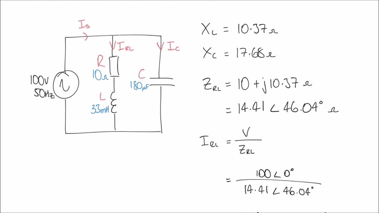
Phasor diagram of parallel rc circuit
Circuit rc phasorUsing phasor diagrams to evaluate series and true parallel rlc ac Phasor diagram and phasor algebra used in ac circuitsAc circuit phasor diagram impedance.
.