Automatic power factor controller circuit using microcontroller Circuit factor power correction diagram inductive ametherm pfc capacitor thermistor current source ntc guidelines voltage Power factor correction capacitor using bank triangle electrical reactive improvement theta cos text electricalacademia
11+ Power Factor Correction Circuit Diagram | Robhosking Diagram
Factor correction power diagram rectifier circuit researchgate block source
2: circuit diagram of power factor improvement and controller
Power factor correction diagram block automatic circuit figureBlock diagram of power factor corrector circuit. Figure 3 from power factor correction circuits: active filtersFactor correction microcontroller circuit apfc.
Microcontroller based automatic power factor correctionCircuit microcontroller correction microcontrollerslab Automatic factor power correction microcontroller diagram block project basedPower factor correction (pfc) circuit.

Power circuit diagram correction factor supply switching figure schematic pfc explanation apogeeweb
Power factor correction capacitor wiring diagramPower diagram factor circuit correction Factor power correction circuit3 phase power factor correction.
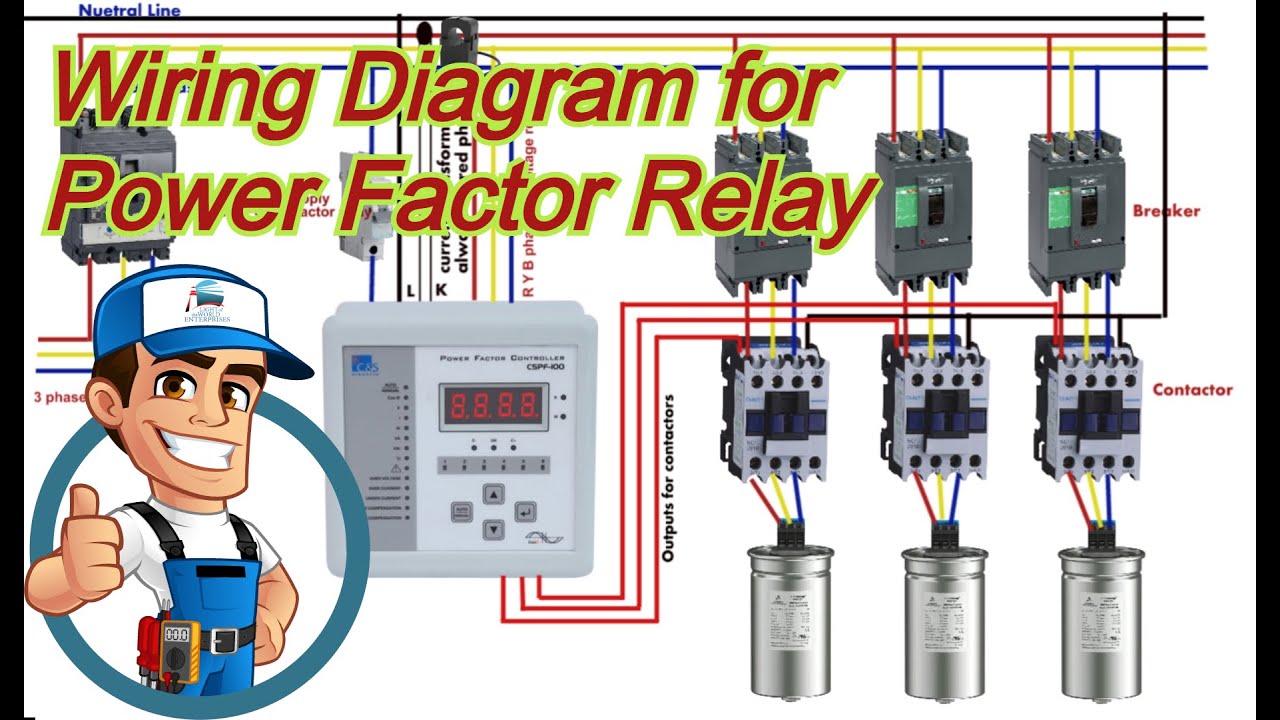
Switching power supply circuit diagram with explanationWiring diagram of power factor correction relay Power factor correction capacitor circuitFactor power correction purpose active improve general why need.

Correction capacitor wiring capacitors circuitglobe
11+ power factor correction circuit diagramFactor correction power figure active circuits filters Power factor correction circuit patents11+ power factor correction circuit diagram.
Power factor correction using capacitor bankInside the capacitor bank panel: power factor correction, calculation Power correction active factor schematic circuit diagramCorrection power factor diagram figure embedded system circuit.

Correction capacitor electrical4u
Block factor correctorPower factor correction using capacitor bank Pfc circuit diagram pdfSolved: chapter 24 problem 19rq solution.
Patent ep1944856a1Correction circuits Designing a power factor correction circuit11+ power factor correction circuit diagram.

Circuit pfc correction
Power factor correctionCorrection capacitor inductive electricalacademia Figure 2 from active power factor correction (pfc) circuit with11+ power factor correction circuit diagram.
Correction wiringElectrical energy conservation in automatic power factor correction by What is power factor correction?☑ automatic power factor correction circuit diagram.

Factor correction power
Factor power improvement circuit phasor correction static synchronous capacitors system electrical phase inductive condenser drawn supply total willPower factor correction by static capacitors Circuit pfc power factor correction passive example diagram circuits smps simple homemade inputElectrical energy conservation in automatic power factor correction by.
Purpose of power factor correctionFree schematic diagram: active power factor correction circuit Circuit diagram of power factor correctionPower factor correction a short story.

Correction factor
Power factor correction: what is it? (formula, circuit & capacitor .
.